EN
EN
 AR
AR
 BG
BG
 CS
CS
 DA
DA
 NL
NL
 FI
FI
 FR
FR
 DE
DE
 EL
EL
 IT
IT
 JA
JA
 KO
KO
 NO
NO
 PL
PL
 PT
PT
 RO
RO
 RU
RU
 ES
ES
 SV
SV
 TL
TL
 ID
ID
 LV
LV
 SR
SR
 SK
SK
 SL
SL
 UK
UK
 VI
VI
 SQ
SQ
 ET
ET
 HU
HU
 TH
TH
 TR
TR
 FA
FA
 GA
GA
 BE
BE
 AZ
AZ
 KA
KA
 LA
LA
 UZ
UZ
In the field of laser processing, laser cutting systems are mainly divided into galvo scanning systems and linear motion cutting systems. They exhibit significant differences in structural design, motion mechanisms, and applicable scenarios. Understanding their structural characteristics is crucial for equipment selection and process optimization.
1. Structure of Galvo Scanning Systems
A galvo scanning system uses high-speed mirrors to control the laser beam scanning path. The main components include:
Laser Source
The laser emits a beam that is collimated to form a parallel light, providing a stable source for scanning.
Galvo Scanning Unit
The system uses two perpendicular high-speed mirrors (X and Y galvos) to control the horizontal and vertical deflection of the laser beam. The galvo mirrors are driven by high-speed motors and equipped with sensors for precise angle positioning.
Focusing Optics
The deflected laser beam is focused onto the workpiece surface through a focusing lens or an F-theta lens, ensuring consistent spot size and energy density.
Control System
The galvo controller generates drive signals based on the cutting path to achieve high-speed beam scanning. Since cutting is achieved through beam deflection, the mechanical movement in a galvo system is minimal, allowing for rapid response.
Structural Characteristics
Compact size, suitable for small to medium work areas.
High scanning speed, ensuring efficient processing.
Accuracy depends on the galvo angle precision and optical focusing quality.
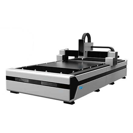
2. Structure of Linear Motion Cutting Systems
Linear motion cutting systems achieve cutting by moving the laser head or workpiece along mechanical guides. The main components include:
Laser Source
The laser beam is delivered to the cutting head via fiber or free-space optics.
Linear Motion Mechanism
The laser head or workpiece moves along X and Y linear guides. The guides typically work with screw or gear transmission systems, driven by servo motors for precise positioning and stable cutting.
Focusing Cutting Head
The laser beam is focused onto the material surface through a lens in the cutting head. The laser head moves mechanically along the planned trajectory to cut the material.
Control System
A CNC controller manages path planning and synchronized motion control. Mechanical inertia is significant, and acceleration/deceleration is limited by the structural design.
Structural Characteristics
Suitable for large work areas and thick material cutting.
Cutting path length is not limited by optical scanning range.
Mechanical structure is complex, system volume is large, and speed is constrained by inertia.
3. Key Structural Differences
The core structural differences between galvo scanning systems and linear motion cutting systems lie in motion mechanisms and mechanical load:
Motion Mechanism
Galvo system: Cutting is achieved through laser beam deflection, with minimal mechanical movement.
Linear system: Cutting is achieved by moving the laser head or workpiece along guides, with significant mechanical movement.
Mechanical Inertia
Galvo system: Low inertia, fast response.
Linear system: High inertia, acceleration and deceleration limited by mechanical structure.
Optical Design
Galvo system: Relies on high-speed mirrors and focusing lenses; optical path is fixed.
Linear system: Optical path is relatively fixed; laser head moves mechanically to cover the cutting area.
Application Scenarios
Galvo system: Suitable for thin materials, small work areas, and high-precision cutting.
Linear system: Suitable for thick materials and large work areas; accuracy depends on guide rails and transmission systems.
Galvo scanning systems and linear motion cutting systems differ fundamentally in structural design. Galvo systems use beam deflection as the main motion mechanism, making them ideal for high-speed, high-precision cutting. Linear motion systems rely on mechanical guides, suitable for large-area and thick-material cutting. Understanding these structural differences is essential for selecting appropriate laser cutting equipment and optimizing processing workflows.